So about 5 years ago, a coworker was going to teach me electronics.
Starting with something simple: stepper motor controller.
List in hand, I bought diodes, resistors, and power MOSFETs. I scavenged a stepper from an old printer. And left in all in a drawer for 5 years.
Finally, I pulled it out of the drawer and started working on it.
The stepper motor turned out to be Bipolar Stepper Motor with 4 wires: 2 independent coils.
The drive circuit is basically an H-Bridge. This allows a low power/low voltage controller (like a PIC) to drive a high current/high voltage (1A @ 12-24V).
Power MOFSET

So I had a lot of trouble figuring out that the Source pin goes to low voltage (source of electrons) and the Drain pin goes to high voltage (absorbs electrons). Basic electricity, but it still took me a while.
Most of the circuits used transistors in lieu of MOSFETs or to control on/off ahead of MOSFETs. Eventually I found a simplified diagram using just MOSFETs.
Basic diagram:

Layout for breadboard:

My actual breadboard:

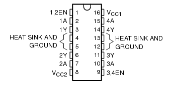
Of course all of this already exists in a simple IC, L293D Dual H-Bridge. Although, I suppose my set up can handle more current, the 16 pin IC is very clean.

No comments:
Post a Comment