Sunday, September 19, 2010

68HC11 Bootstrap mode

In 1999, I received a Super T-Comp; a 68HC11 based microcontroller board that is similar to the Handyboard.
While working with it I released the sacred smoke. I blew out 3 chips.
I repaired the damage, but I couldn't get it to work right again. So it sat in my toybox waiting for me to try again.

In 2010, I am taking a class in embedded systems; so it is time to try again.

Inspecting the board again, I found a bad chip that I missed; a NAND gate driving the external RAM. I will fix that this week.

Regardless I should be able to talk to T-Comp in Bootstrap mode. PCBug11 is the original tool for talking to 68HC11. It doesn't run on modern (fast) computers.

So I tried TeraTerm terminal software. Finally did established communication this morning.

68HC11 has 4 modes:
Single Chip: no external RAM
Expanded: external RAM
Bootstrap: single chip, using bootstrap loader in ROM
Test: Uh? don't know

Bootstrap Mode
Hold ModA and ModB low
Toggle Reset
Release ModA and ModB
within a second
send a byte over SCI (serial port) at 1200 Baud, No parity, 8 bits, 1 stop bit.

It is now ready to accept a 256 byte program. 68HC11 will echo bytes. Once it recieves 256 bytes, the program counter resets to $0000 and starts to run the loaded program. In theory.

Saturday, September 18, 2010

Hacking the PSP

Everyone has hacked the PSP to put non-Sony firmware on.
You can still run your games, AND install homebrew stuff.

This was the original goal when I bought my PSP. I got distracted by actually playing games.
I finally got around to doing it.

I have the GOW edition PSP slim, it had Sony firmware V3.94 installed.

I sort of followed the instructions that I found here

Things you need:
Pandora Battery - modified battery to allow access to the PSP bootstrap mode,
I borrowed one
Sony memory stick - 1Gb stick works fine
PSP Grader v0.008 - installs firmware, I got it here
modified PSP firmware - overwrites the Sony firmware, I got it here

Connect the PSP to your PC; start USB mode.
Copy the Sony memory stick to PC
Format the Sony memory stick

Start PSP Grader
Locate the eboot.pbp in the PSP_500_FW.zip
Download file to stick

Disconnect and power off the PSP
Remove battery
Insert memory stick (if you haven't)
Hold down the L button
Insert the Pandora Battery (often PSP auto-starts) and start PSP
Back up NAND
Restart PSP
Install 5.00 M33 (or similar)

Done.
I have spent all my time playing a Magic the Gathering Homebrew (Wagic) in stead of programming anything.

Wednesday, June 2, 2010

Shelves Part V - Vini Vidi Vici!

Actually, I finished the shelves by the end of the last post, but the completed shelves deserve a private showing.

TaDa!
Amazing! Beautiful!
And with stuff...

less beautiful, but nothing is overflowing.

Shelves Part IIII - Install!

Problem with the shelves is that they won't fit in the pantry with the shelves intact. As designed, the shelves are attached to the back board from the rear. Thus I can't screw the individual shelves back in place given the tiny space behind the back boards in the pantry.

Instead I decided to add supports to the back boards, under the shelves. The supports will be screwed in from the rear. Then after the unit is installed I can add the individual shelves from the front.

Out of concern that the full shelves were too heavy to attach solely to the wall, I added support legs.

Sunday morning I ran out to my local hardware store.
I picked up 12 feet of 1" x 2" board.
I cut out 12 boards, rounded the edges and stained them.
Then I went on vacation.

First the legs:

Then mount the back boards to the wall and the legs:

Then add each shelf, screwing the supports from the bottom:

Saturday, May 29, 2010

Shelves Part III - Aw Crud

Time to install.

I emptied the pantry and started removing shelves.
The contents are scattered about the kitchen.

So I started the installation process.
I ran into a small problem. It won't fit in the door.
Initially, I planned to install the backboards, then the shelves.
Installation would have been easy as pie.

But somewhere along the line, I changed my mind, and assembled it first.
Oops. I can't get it inside the closet. No matter how much twisting, shaking, lifting, grunting I do, one corner sticks out. Oh Crud.
I have a plan to fix it. I can install supports under the shelves. Wish me luck.

Monday, May 17, 2010

Shelves Part II - Stained

I hesitated about staining the shelves. Somebody pointed out, "it's in a closet, go for it".
I chose a dark red (Minwax Red Oak 215).
I worried about the stain on the edges of the plywood.

There were a few spots where the dado cuts chipped the plywood, so I looked into wood filler.
I tried the Minwax Stainable Wood Filler. It looks/feels like beach sand. Odd.
Seemed to blend okay.
Test everything on scrap first!
The stain was much darker than I expected (brown, not red)
It did not look good on the edges of the plywood.
But it looked worse on the edges with the wood filler. (I think)

Well, I used the wood filler on the deep gouges, but not on the edges.
I sanded everything with 220 grit sandpaper and an orbital sander. Fairly quick job.

I applied 2 coats of 215 (2x 8oz cans, no left overs). 6 hours after each coat.
FYI the stainable wood filler doesn't stain. (the yellow stripe just above the shelves)

Applied a coat of Minwax Fast Drying Polyurethane (32 oz can, used less than a 1/4) to all of the stained surfaces.

After 6 hours, I felt the surface. Very rough.
So I lightly sanded (220 grit) the top of the shelves.
Applied another coat (again just to the top of the shelves)
24 hour cure. Very nice!

Most important thing I learned: I need more light.
I found a few spots where I missed stain or clear coat.

Next I need to figure out how to mount it.

One last thing. Remember to clean the stickers off with rubbing alcohol first.


Sunday, May 16, 2010

Woodworking Project

I took a woodworking class at the community college. But what to do for a project?

Someone pointed out the hell that is the pantry.
I have a project now.

The pantry is in a tight corner. The current shelving is 8"x2' wire mesh. It uses less than 1/3 of the space in the pantry.

My proposed shelves are basically 2'x2' triangles (with additional 4" of overhang). This should provide a lot more space.

I should have documented the individual pieces before assembling them. Oops.
Stats:
  • 3/4" plywood backing (1/4" deep dado cuts for the shelves)
  • four 1/2" plywood shelves
  • two 3/4" plywood shelves ( from the leftover from the backing)
  • 11.5" between the shelves
  • top shelf is cut much deeper (not triangular) so I can reach stuff on the top.
After assembling the shelves, I decided to round the edges (better late than never) .
I bought a router and bits (cool toy!).
I used a 3/8" round-over. The bit is recessed to 1/8" cutting surface.
I like the final look.
The next step is stain and protect.

Thursday, January 7, 2010

Motor Lockout and Timer

I need a remote box to control the RPM of a 20 HP rotor.
Since, the AC Drive provides 90% of the work, the remote box is a pretty easy task.

It has 4 parts:
10-turn rotary potentiometer - vary rotor speed from 0-12000RPM,
Kill switch - big red button that cuts power to the motor if something goes wrong
Something ALWAYS goes wrong
Enable switch - small button that lets command from the AC Drive go to the motor
Lock out - timer that makes sure the command from the AC Drive is zero before letting you use the Enable switch

The diagram is shown below:

The red lines S1, Sc:
If S1 is connected to Sc, then the Drive commands reach the motor.
Ultimately, the circuit will connect S1 to Sc if Enable switch is hit.

Av, A1, Ac:
10-turn pot to control RPM.
This is a basic voltage divider; the Drive senses the reference voltage (Av) compared to A1.

Enable Switch and Panic Button:
The yellow block is a 3PDT 5V relay.
When the coil is energized by pressing the Enable button:
Pole 1 connects the main coil to 5V. Thus the coil stays energized after the Enable button is released.
Pole 2 connects S1 to Sc.
Pole 3 energizes the Green LED.

When the Panic button (normally closed) is pressed, it breaks the circuit and opens the coil.

Once the circuit is enabled, the Panic button is the only way to kill it.

The key is that NOTHING happens if the lockout transistor (NPN) is not energized by the output of the Safety Lockout. This transistor acts as a normally-open switch.

Safety Lockout:
This is borrowed in whole from www.doctronics.com, "retriggerable monostable timer"

The input signal is an RPM pulse train (0-10V), this goes through a voltage divider (0-5V), and an inverter (the monostable likes HI inputs).

The 555 timer is used to create a monostable timer.
The output (pin 3, green line) goes HI when the input (pin 2) has a falling edge.
Output is HI for 15 seconds (1.1*900K Ohms*15microF).
Red LED turns on to indicate Output is HI.

Basically, if there is a pulse train coming in, then the output goes HI for 15 seconds and stops you from enabling the relay. ( If it is already enabled, then there is no effect.)
The problem is that the 15 seconds starts from the first falling edge; additional pulses don't reset the timer.
Enter the "retrigger transistor"
Every time the input is LO (PNP) the capacitor is discharged and must slowly recharge.
This resets the 15-second timer after each pulse.

The actual circuit wired up on the bread board is shown below.
The rightmost button would be replaced by the RPM pulse train.
The center button would be replaced by a "normally closed switch"
And the left LED should be GREEN.


Tuesday, January 5, 2010

Bipolar Stepper Motor circuit

So about 5 years ago, a coworker was going to teach me electronics.
Starting with something simple: stepper motor controller.

List in hand, I bought diodes, resistors, and power MOSFETs. I scavenged a stepper from an old printer. And left in all in a drawer for 5 years.

Finally, I pulled it out of the drawer and started working on it.

The stepper motor turned out to be Bipolar Stepper Motor with 4 wires: 2 independent coils.

The drive circuit is basically an H-Bridge. This allows a low power/low voltage controller (like a PIC) to drive a high current/high voltage (1A @ 12-24V).

Power MOFSET

So I had a lot of trouble figuring out that the Source pin goes to low voltage (source of electrons) and the Drain pin goes to high voltage (absorbs electrons). Basic electricity, but it still took me a while.

Most of the circuits used transistors in lieu of MOSFETs or to control on/off ahead of MOSFETs. Eventually I found a simplified diagram using just MOSFETs.

Basic diagram:

Layout for breadboard:


My actual breadboard:

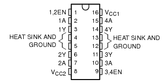
Of course all of this already exists in a simple IC, L293D Dual H-Bridge. Although, I suppose my set up can handle more current, the 16 pin IC is very clean.